arrow_back Back home
15 June 2021Aligning the Lidars (with a video!)
What’s Lidar, and why use it?
For all the complexities and quandaries involved in autonomous driving, robot cars only need to do three main things:
- Look at the world
- Make decisions based on what is seen
- Act on those decisions
I’ve mentioned before that I’m working on Project Voltron (our self-driving car project– the name wasn’t mine) with a group of talented classmates. We’re busy finding answers to items 1 and 3, and we’re borrowing heavily from open source code for item 2.
Lately I’ve been personally focusing on item 1. What’s a good way for a car to see the world? Many systems, most notably Tesla’s Autopilot, rely entirely on cameras. Other systems throw radar into the mix. At the moment, our project uses Lidar exclusively.
Lidar sensors bounce lasers off nearby objects and measure how long it takes for the laser beams to return. This gives rich information about object position and reflectivity (but not color). So while a Lidar sensor could tell me that a stop sign is 15.43 feet ahead of us, and that the stop sign is unusually shiny, it couldn’t confirm that the stop sign is red, or that the stop sign says “STOP”.
At the moment, we care much more about the 3D shape of our environment than about how green a pedestrian’s shirt is. Shape is more useful for localization, since navigational landmarks like curbs and fountains stick out more in 3D.
Getting things working
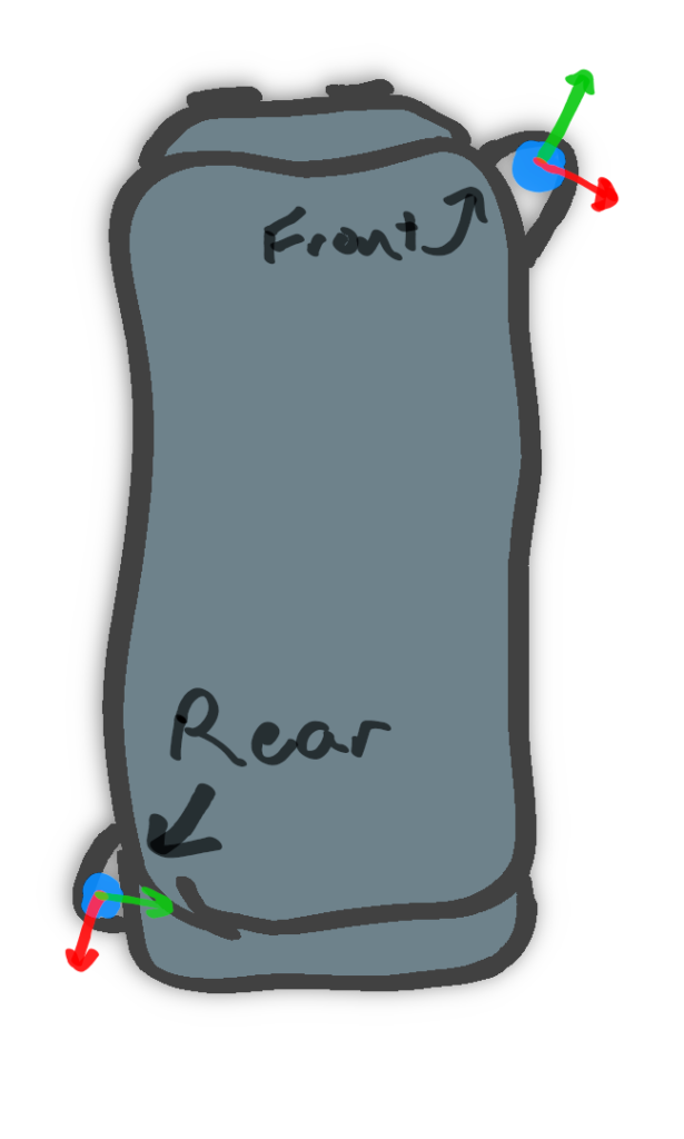 Our car has two Lidar sensors, which eliminates blindspots.
Our hardware is pretty standard: two Velodyne “Pucks”. We place them in opposite corners of the car (though not on the roof), which creates a 360-degree view around the car.
But Lidars aren’t as simple as plugging them in, especially when you want to use more than one at a time. Each Lidar, like any other kind of observer in the world, has its own frame of reference. What’s on the left of one sensor might be behind another sensor. In the image above, I drew the axes of each sensor– notice how they don’t match up.
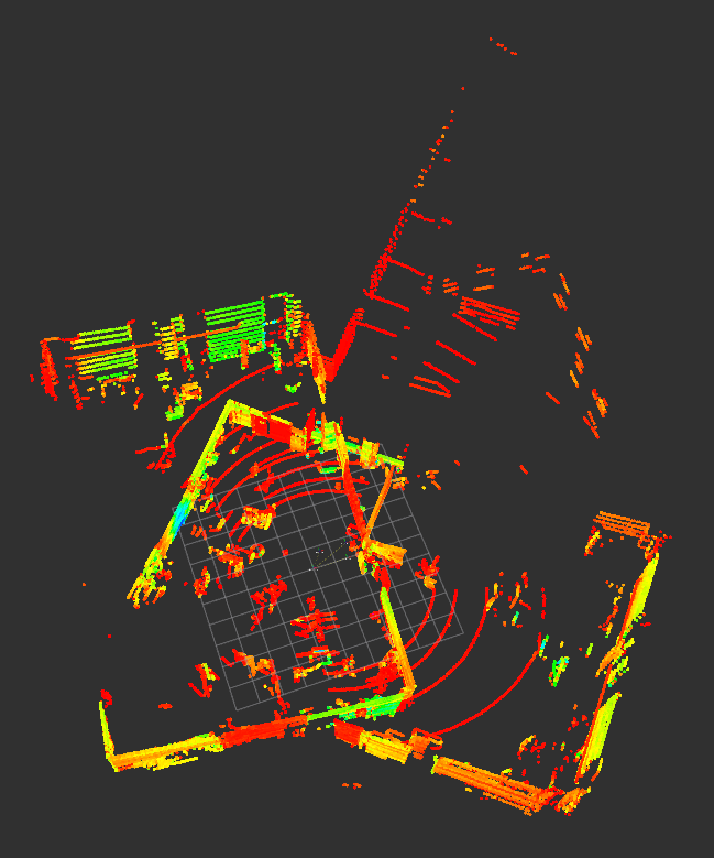 Without any calibration, our two Lidars produce an image like this. Gross! Notice the same rectangular room, but skewed.
This week I worked on aligning the two sensors so that our combined image isn’t skewed like above. Once I figured out the right approach, it’s actually pretty intuitive. First, I described where each sensor was located relative to the center of the vehicle. When we describe how a point is translated and rotated from one frame of reference to another (the center of the vehicle to a Lidar sensor, in this case), we call this a “transform”.
We put two transforms, one for each Lidar from the center of the vehicle, into a special file called “voltron.urdf”. URDF stands for the Universal Robot Description Format, and it’s an xml-based standard for describing how robots look and physically behave.
Our very basic voltron.urdf looks something like this:
Notice the two “joints”, which are really just transforms from the center of the car (“base_link”) to each sensor. Each joint has a translation (xyz) and rotation (rpy– roll, pitch, yaw).
We’re nearly there! I needed to add transforms in one other place: the parameter files for our Lidar filter nodes. These nodes (executables) are where unneeded points are scrubbed away, leaving a simplified image. The finished param for the front Lidar looked like this:
The alignment happens in the “static_transformer” section. It’s similar to the URDF, except that the translation is represented as a quaternion (see end to learn more).
Alignment demonstration video
Whew, the two Lidars are finally lined up! On Saturday, I drove the car around to test the fused data:
I should note that the car is obviously not driving itself. That comes later! Right now, we’re simply seeing what the car sees. The sensor data goes through a few stages before appearing here in the demo.
First, the raw points are filtered so that unneeded points are removed (scans of the vehicle itself, for example). Then the points are translated and rotated into the vehicle’s common reference frame. The points from both sensors are then fused together into a single stream. Finally, the points are downsampled (simplified) to streamline our algorithms’ performance.
What’s next?
Now that our 3D data is ready to use, we’re working on creating a 3D scan of campus. I’ll save the details of that for a future post.
Footnote: What’s a quaternion?
Mere mortals like me most easily picture rotations in terms of a roll, a pitch, and a yaw. In fact, I sometimes hold my hand up and imagine that it’s an airplane. Then I imagine this:
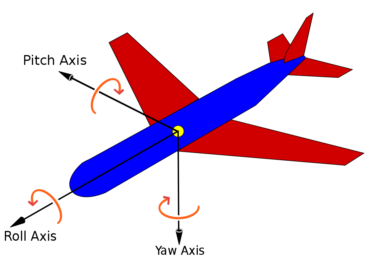 Yaw_Axis.svg: Auawisederivative work: Jrvz, CC BY-SA 3.0 https://creativecommons.org/licenses/by-sa/3.0, via Wikimedia Commons
Well, it turns out that roll-pitch-yaw (RPY) has a few issues that make it unstable in serious applications. It’s also awkward for computers to make sense of (they don’t have hands or imaginations). Thankfully, mathematicians have given us a better solution in quaternions, which are more stable and easier to compute. They just take a bit of work to understand.
I will not presume that I can explain quaternions properly, since I’ve only just begun to understand them myself. However, I’ll try to offer the basics. Imagine we have a vector q and we’d like to rotate a point p about this vector.
Because I’m a simpleton, I think of holding my index finger in the air (q) and imagine a bee buzzing around it (p). This bee will obediently buzz around my finger no matter where I point it. The question is: Given that I point my finger in a direction such that
\[q = \cos(\frac{\theta}{2}) + \sin(\frac{\theta}{2})\langle x, y, z \rangle = w + x*i + y*j + z*k\]and such that
\[p = (x, y, z)\]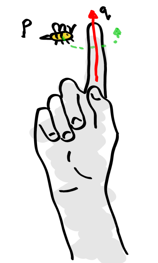
My finger and a bee.
Then we can describe the rotation of p about q with the equation \(f(p) = q*p*q^-1\)
where is the new location after the rotation is applied.
Why’s called a quaternion? It’s described in four components: w, x, y, and z. It turns out that rotations in 3D space require not three but four components.
You can find some much smarter people explain quaternions here: