arrow_back Back home
19 November 2023Structure from motion
Huge thank you to Chahat Deep Singh’s article on SFM here. These are basically a rehash of his article, as well as chapter 7 of Computer Vision: Algorithms and Applications by Richard Szeliski.
Introduction
Structure from motion, or SfM, is the process of simultaneously estimating a series of camera poses and the 3D structure of a scene using a sequence of 2D images. SfM has the following steps, each of which I’ll cover here:
- Feature matching and outlier rejection using RANSAC
- Fundamental matrix estimation
- Essential matrix estimation using the result from (2)
- Camera pose estimation using the result from (3)
- Using triangulation to check for chirality
- Projecting points into 3D
1. Feature matching, the fundamental matrix, and RANSAC
1.1. The fundamental matrix and epipolar geometry
The fundamental matrix $F \in \R^{3 \times 3}$ is a rank-2 matrix that relates the corresponding set of points between two images with different viewpoints. We use epipolar geometry, the math behind stereo imagery, to derive the fundamental matrix. Epipolar geometry is the intrinsic projective geometry between two views. It depends only on the camera parameters (the $K$ matrix) and the relative pose between the two views. In other words, epipolar geometry and $F$ are independent of the scene being captured.
1.2. Epipolar geometry
Consider a 3D point $X$ viewed as a 2D point $x$ in one image and as $x’$ in a second. Let the respective camera centers be $C, C’$.
The points $x, x’, X$ (and also $C, C’, X$) form a plane that we label $\pi$, i.e. $\vec{Cx}\cdot (\vec{CC’} \times \vec{C’x’}) = 0$.
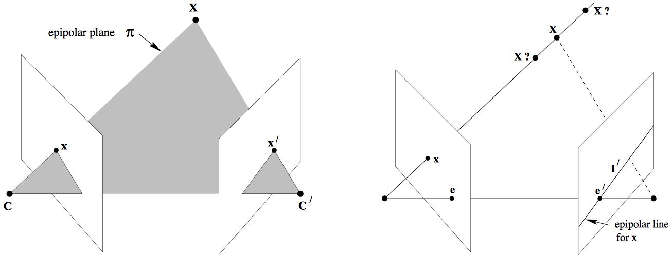
The epipolar plane $\pi$ (left) and the epipolar line $l’$ (right).
Say we only know $x$, not $x’$. In other words, we only know that the 3D point $X$ corresponds to some image point $x$, but we don’t know its matching point in the second image. Since the correspondences are constrained along the epipolar plane $\pi$, the possible locations for $x’$ form an epipolar line $l’$. Knowing $l’$ is extremely useful, as it reduces the search space for $x’$ from the entire second camera image to a single line.
Some terminology:
- A camera’s epipole is the point of intersection of a camera’s image plane and the line connecting the two camera’s centers. See $e, e’$ above.
- We call the line connecting the camera centers, $\vec{CC’}$, the baseline.
- The epipolar plane is the plane containing both the baseline and our 3D point $X$.
- The epipolar line for a given camera is the intersection of the epipolar plane with the camera’s image plane. All epipolar lines intersect at the epipole.
2. Computing the fundamental matrix
We can solve for $F$ by first applying the epipolar constraint: \(x_i'^T F x_i = 0\) for each correspondence $i \in {1,\cdots,m}$. We also call this the Longuet-Higgins equation or simply the correspondence condition. Since $F$ is $3 \times 3$, we can solve it with a homogenous linear system with nine unknowns/DOFs. Expanding this yields: $$
\begin{bmatrix} x_i’ & y_i’ & 1 \end{bmatrix}
\begin{bmatrix}
f_{11} & f_{12} & f_{13}
f_{21} & f_{22} & f_{23}
f_{31} & f_{32} & f_{33}
\end{bmatrix}
\begin{bmatrix} x_i \ y_i \ 1 \end{bmatrix} = 0 \(Given $m$ correspondences, we can rework the above into:\)
\begin{bmatrix}
x_1x_1’ & x_1y_1’ & x_1 & y_1x_1’ & y_1y_1’ & y_1 & x_1’ & y_1’ & 1
\vdots & \vdots & \vdots & \vdots & \vdots & \vdots & \vdots & \vdots & \vdots
x_mx_m’ & x_my_m’ & x_m & y_mx_m’ & y_my_m’ & y_m & x_m’ & y_m’ & 1
\end{bmatrix}
\begin{bmatrix}
f_{11} \ f_{21} \ f_{31}
f_{12} \ f_{22} \ f_{32}
f_{13} \ f_{23} \ f_{33}
\end{bmatrix} = 0
$$
Since the above linear equation has 9 unknowns, we require 8 constraints, or points, to solve it. We therefore refer to this as the eight-point algorithm. We can solve it using singular value decomposition, or SVD.
One last consideration: When solving in real-world systems, we’ll arrive at an approximated $F$ that includes a bit of noise, which results in a rank of 3, not 2 as in the perfect case. For the epipolar geometry to work properly, we need rank 2. To enforce this, we set the last singular value from SVD to be zero. This forces our null space to be non-empty, and therefore cause all of our epipolar lines to cross at a single point (our desired behavior). See below:
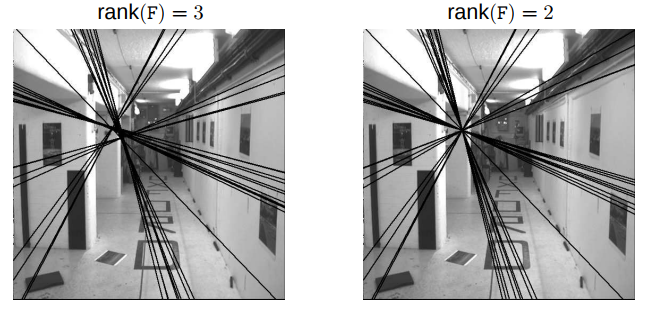
If we don’t properly constrain our rank to equal 2, then the epipolar lines fail to meet at a single point.
2.1. Rejecting outliers with RANSAC
We don’t consider the process by which point correspondences between two images are found. We assume that they’re provided to us from some upstream algorithm, such as SIFT, that is imperfect and therefore includes a few bad results– outliers. We need to remove these outliers before we can properly reconstruct our scene in 3D.
Enter our hero, RANSAC. We first estimate the matrix $F$ using SVD against all correspondences as outlined above. Given a set of many correspondences, RANSAC then randomly selects 8 points. It compares the “fit” of each correspondence against $F$. RANSAC repeats this process many times, returning the set of 8 correspondences with the greatest average fit.
3. The essential matrix
We’ve estimated the fundamental matrix $F$, which relates each point $x$ in one image with its corresponding point $x’$ in a second image. But $F$ does not provide any “metric” context. In other words, it does not leverage the camera’s intrinsic parameters to get a true, physical measurement of the scene or the relative pose between the two images.
That’s the job of the essential matrix, which combines $F$ with our camera’s intrinsic matrix $K$: \(E=K^TFK\) As is the case with estimating $F$, our initial $E$ estimate may include some noise that cause our singular values to be unequal to $(1,1,0)$. We can correct this by applying: \(E=U \begin{bmatrix} 1 & 0 & 0 \\ 0 & 1 & 0 \\ 0 & 0 & 0 \end{bmatrix}V^T \\\) (see Szeliski 7.2).
4. Estimating camera pose
When estimating the relative pose between two cameras, it turns out that there are actually four possible camera pose configurations, not two: $(C_n,R_n) , n\in (1,4)$, where $C$ is the camera center and $R\in SO(3)$ is the rotation matrix.
Let our essential matrix found earlier also be: $E=UDV^T$, and let $W = R_{z,\pi/2}$ or: \(W=\begin{bmatrix} 0 & -1 & 0 \\ 1 & 0 & 0 \\ 0 & 0 & 1 \end{bmatrix}\) Then the four possible configurations are:
- $C_1=U(:,3), R_1=UWV^T$
- $C_2=-U(:,3), R_2=UWV^T$
- $C_3=U(:,3), R_3=UW^TV^T$
- $C_4=-U(:,3), R_4=UW^TV^T$
Note that if $\det(R)=-1$, then we must correct the pose by setting $C=-C, R=-R$. In other words, $\det(R)$ should always equal 1.
5. Checking for chirality using triangulation
As noted above, the essential matrix yields ambiguous camera poses– four possible poses instead of two. We resolve this ambiguity by checking the chirality condition for each pose.
Given two possible camera poses, triangulate all of the 3D points. Then check the sign of the depth $z$ for each point. If the depth is negative, that means that the points are being reconstructed behind the cameras, and so the two poses form an invalid combination.
Specifically, a 3D point $X$ is behind the camera iff $r_3(X-C) <0$, where $r_3$ is the third row of the rotation matrix (the z axis of the camera). Why bother triangulating all points $X$ for a given pair of camera poses and correspondences, instead of just checking a condition for a single point and assuming it holds for the rest? Because correspondence noise often causes the chirality condition to fail for some points even in good pose pairs. So we say that the best camera configuration $(C,R,X)$ is the one that has the greatest number of points placed ahead of the camera.
6. Projecting points into 3D
After we’ve triangulated all image points $\vec{x}$, we’re nearly there. For each pixel coordinate pair from the two cameras, we convert them into normalized homogenous coordinates $(u, v, 1)$ and $(u’, v’, 1)$. Then, supplied with projection matrices for both cameras, $P_1, P_2$, we form a matrix $A$ like so: $$ A=\begin{bmatrix}
v p_3^\intercal - p_2^\intercal
p_1^\intercal - up_3^\intercal
v’p_3’^\intercal - p_2’^\intercal
p_1’^\intercal - u’p_3’^\intercal
\end{bmatrix} $$ To find the corresponding 3D point given the coordinate pairs, we form the equation $Ax=0$ and solve for $x$ using Singular Value Decomposition. This yields a matrix $V_h$, for which our 3D point lies in the final row.
We repeat this, forming $A$ and solving for $x$ using SVD, for every pixel coordinate pair between the two images. Keep in mind that the projection matrices are both slightly noisy, and so the 3D points will have error accordingly.
Recap
Structure from motion is the simultaneous estimation of:
- The relative transform of the camera at two (or more) distinct times, and
- The 3D structure of a scene captured by two (or more) images corresponding to each time.
Given a set of correspondences between the images, which we calculate beforehand with some other algorithm, we use a special kind of stereo math called epipolar geometry to constrain our search space and reject any noisy correspondences using RANSAC.
RANSAC selects the best four correspondences (the eight points that produce the least squared error). We then use the eight point algorithm to find the fundamental matrix $F$, which combines with our camera’s intrinsic parameters to form an essential matrix $E$. Finally, we use $E$ to convert our correspondences into 3D points.